 What is a high frequency variable load inverter architecture?This thesis presents a high frequency variable load inverter architecture along with a physical prototype and e ciency optimizing controller. The inverter architecture consists of two constituent inverters, one connected directly through the load and the other connected through an immittance converter, which acts as a lossless power combiner.
What is a high frequency inverter?In many applications, it is important for an inverter to be lightweight and of a relatively small size. This can be achieved by using a High-Frequency Inverter that involves an isolated DC-DC stage (Voltage Fed Push-Pull/Full Bridge) and the DC-AC section, which provides the AC output.
Which power supply topologies are suitable for a high frequency inverter?The power supply topologies suitable for the High-Frequency Inverter includes push-pull, half-bridge and the full-bridge converter as the core operation occurs in both the quadrants, thereby, increasing the power handling capability to twice of that of the converters operating in single quadrant (forward and flyback converter).
Can a high-frequency variable load inverter directly drive widely variable loads?Typically a tunable matching network is used to transform the varying load into a ciency and impairing transient response. This thesis presents the design, physical prototype, controller, and experimental results of a high-frequency variable load inverter architecture (referred to as HFVLI) that can directly drive widely variable loads.
Can hfvli drive a wide load range RF inverter?From these results it is evident that the HFVLI prototype is successful in the goal of driving a wide load range at high power power levels. rst physical prototype of of a wide load range RF inverter based on the proposed high frequency variable-load inverter topology was designed and built along with an e ciency optimizing controller.
What is the HM scheme for fdcl inverter?heme. The HM scheme is implemented for the ac–ac converter stage. For the FDCL topology, the output stage is+−HF 1 0UTVTWTUUTVVTWWTUBVBWBUUBVVBWWBFIGURE 29.2 Diagram of gate-drive-signal generation for the HFL inverter .where PWMx (x D a, b, or c) denotes theinary compara-tor output between refere
What is a high frequency variable load inverter architecture?This thesis presents a high frequency variable load inverter architecture along with a physical prototype and e ciency optimizing controller. The inverter architecture consists of two constituent inverters, one connected directly through the load and the other connected through an immittance converter, which acts as a lossless power combiner.
What is a high frequency inverter?In many applications, it is important for an inverter to be lightweight and of a relatively small size. This can be achieved by using a High-Frequency Inverter that involves an isolated DC-DC stage (Voltage Fed Push-Pull/Full Bridge) and the DC-AC section, which provides the AC output.
Which power supply topologies are suitable for a high frequency inverter?The power supply topologies suitable for the High-Frequency Inverter includes push-pull, half-bridge and the full-bridge converter as the core operation occurs in both the quadrants, thereby, increasing the power handling capability to twice of that of the converters operating in single quadrant (forward and flyback converter).
Can a high-frequency variable load inverter directly drive widely variable loads?Typically a tunable matching network is used to transform the varying load into a ciency and impairing transient response. This thesis presents the design, physical prototype, controller, and experimental results of a high-frequency variable load inverter architecture (referred to as HFVLI) that can directly drive widely variable loads.
Can hfvli drive a wide load range RF inverter?From these results it is evident that the HFVLI prototype is successful in the goal of driving a wide load range at high power power levels. rst physical prototype of of a wide load range RF inverter based on the proposed high frequency variable-load inverter topology was designed and built along with an e ciency optimizing controller.
What is the HM scheme for fdcl inverter?heme. The HM scheme is implemented for the ac–ac converter stage. For the FDCL topology, the output stage is+−HF 1 0UTVTWTUUTVVTWWTUBVBWBUUBVVBWWBFIGURE 29.2 Diagram of gate-drive-signal generation for the HFL inverter .where PWMx (x D a, b, or c) denotes theinary compara-tor output between refere
High-frequency inverters often need to operate under dynamically varying loads, while the inverter structure allows only very narrow loads. In this article, an optimal impedance
Get Price
With the increasing demand for volume reduction and efficiency improvement, very high frequency (VHF) power converters (30–300 MHz)
Get Price
This thesis presents the design, physical prototype, controller, and experimental results of a high-frequency variable load inverter architecture (referred to as HFVLI) that can directly drive
Get Price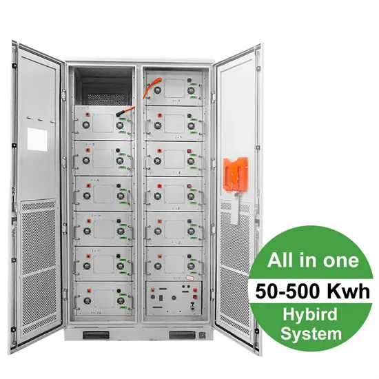
Download scientific diagram | Circuit structure of high-frequency inverter. from publication: Power Quality Control System of High-Power-Density Switching
Get Price
Abstract: In the high-frequency AC (HFAC) power distribution system, problems such as high switching frequency, a complicated circuit configuration and difficult parameter design still exist
Get Price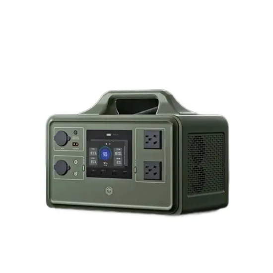
Frequency inverters have always been limited to "normal torque" applications while high torque, low rpm applications have been the domain of DC drives. This has changed recently with the
Get Price
Introduction: A frequency converter, often referred to as a frequency inverter, is a crucial element in many electrical systems. But what exactly lies behind it? Essentially, a
Get Price
This application report documents the concept reference design for the DC-DC Stage and the DC-AC Converter section that can be used in the High-Frequency Inverter using TMS320F28069,
Get Price
The inverter (see Fig. 29.7) described in this section comprises a dc–dc zero-ripple boost converter (ZRBC), which generates a high-voltage dc at its output followed by a soft
Get Price
Kenya''s leading online solar products store for top-quality solar panels, water heaters, inverters, outdoor lighting, water pumps, batteries, and more.
Get Price
Multilevel inverters are uniquely suited for this application because of the high VA ratings possible with these inverters [2, 3]. Where generated ac voltage is available such as from an alternator
Get Price
Schematic diagrams [3] and [4] of (a) coupled inductor structure for reducing the HF current ripple; (b) half-bridge active filter, which compensates for the low-frequency harmonic-current-ripple
Get Price
The inverter circuit creates a high-frequency alternating current that is supplied to the coil. In the case of fluorescent lights, this high-frequency alternating
Get Price
Abstract—Efficient generation and delivery of high-frequency (HF, 3-30 MHz) power into variable load impedances is difficult, resulting in HF inverter (or power amplifier) systems that are
Get Price
A comparative analysis of existing HFLIs in terms of switching frequency, soft-switching capability, modulation strategies, power rating, and efficiency is discussed.
Get Price
Recent research and development efforts in SiC inverters for electric drive applications highlight a strong focus on achieving high power density, high efficiency, and high-frequency operation.
Get Price
Download scientific diagram | Circuit structure of high-frequency inverter. from publication: Power Quality Control System of High-Power-Density Switching Power Supply for Green Environment...
Get Price
In this paper, a multi-level high-frequency inverter structure based on a forward converter is proposed, which ensures that the input and output are electrically isolated.
Get Price
A comparative analysis of existing HFLIs in terms of switching frequency, soft-switching capability, modulation strategies, power rating, and efficiency is discussed.
Get Price
Discover how proper installation and maintenance of power frequency inverters can stabilize Somaliland''s energy infrastructure. This guide covers technical insights, cost-saving strategies,
Get Price
A new method for the design of a bidirectional inverter based on the sinusoidal pulse-width modulation principle and the use of a low-cost and
Get Price
High-Frequency Link inverters (HFLIs) have attracted significant research attention owing to their compact design, high power density, and high efficiency. HFLI systems achieve power
Get Price
Understand the difference between high frequency and low frequency inverters with this quick article.
Get Price
Therefore, it is clear that the design phases of power converters and transformers interact, particularly at high power levels. So, the primary goal of this study is to carry out
Get Price
A high frequency inverter circuit is an electronic circuit that allows for the conversion of DC electricity into AC power with a high frequency, usually around 60 Hz or more.
Get Price
This thesis presents a high frequency variable load inverter architecture along with a physical prototype and e ciency optimizing controller. The inverter architecture consists of two constituent inverters, one connected directly through the load and the other connected through an immittance converter, which acts as a lossless power combiner.
In many applications, it is important for an inverter to be lightweight and of a relatively small size. This can be achieved by using a High-Frequency Inverter that involves an isolated DC-DC stage (Voltage Fed Push-Pull/Full Bridge) and the DC-AC section, which provides the AC output.
The power supply topologies suitable for the High-Frequency Inverter includes push-pull, half-bridge and the full-bridge converter as the core operation occurs in both the quadrants, thereby, increasing the power handling capability to twice of that of the converters operating in single quadrant (forward and flyback converter).
Typically a tunable matching network is used to transform the varying load into a ciency and impairing transient response. This thesis presents the design, physical prototype, controller, and experimental results of a high-frequency variable load inverter architecture (referred to as HFVLI) that can directly drive widely variable loads.
From these results it is evident that the HFVLI prototype is successful in the goal of driving a wide load range at high power power levels. rst physical prototype of of a wide load range RF inverter based on the proposed high frequency variable-load inverter topology was designed and built along with an e ciency optimizing controller.
heme. The HM scheme is implemented for the ac–ac converter stage. For the FDCL topology, the output stage is +−HF 1 0UTVTWTUUTVVTWWTUBVBWBUUBVVBWWBFIGURE 29.2 Diagram of gate-drive-signal generation for the HFL inverter .where PWMx (x D a, b, or c) denotes the inary compara-tor output between reference
 Inverter high frequency hybrid
 High frequency inverter for communication
 Gabon high frequency inverter device manufacturer
 Silicon Carbide High Frequency Inverter
 Is the grid-connected inverter industrial frequency or high frequency
 High frequency inverter price in Latvia
 12v household high frequency sine wave inverter
 UK high frequency inverter price
The global commercial and industrial solar energy storage battery market is experiencing unprecedented growth, with demand increasing by over 400% in the past three years. Large-scale battery storage solutions now account for approximately 45% of all new commercial solar installations worldwide. North America leads with a 42% market share, driven by corporate sustainability goals and federal investment tax credits that reduce total system costs by 30-35%. Europe follows with a 35% market share, where standardized industrial storage designs have cut installation timelines by 60% compared to custom solutions. Asia-Pacific represents the fastest-growing region at a 50% CAGR, with manufacturing innovations reducing system prices by 20% annually. Emerging markets are adopting commercial storage for peak shaving and energy cost reduction, with typical payback periods of 3-6 years. Modern industrial installations now feature integrated systems with 50kWh to multi-megawatt capacity at costs below $500/kWh for complete energy solutions.
Technological advancements are dramatically improving solar energy storage battery performance while reducing costs for commercial applications. Next-generation battery management systems maintain optimal performance with 50% less energy loss, extending battery lifespan to 20+ years. Standardized plug-and-play designs have reduced installation costs from $1,000/kW to $550/kW since 2022. Smart integration features now allow industrial systems to operate as virtual power plants, increasing business savings by 40% through time-of-use optimization and grid services. Safety innovations including multi-stage protection and thermal management systems have reduced insurance premiums by 30% for commercial storage installations. New modular designs enable capacity expansion through simple battery additions at just $450/kWh for incremental storage. These innovations have significantly improved ROI, with commercial projects typically achieving payback in 4-7 years depending on local electricity rates and incentive programs. Recent pricing trends show standard industrial systems (50-100kWh) starting at $25,000 and premium systems (200-500kWh) from $100,000, with flexible financing options available for businesses.